
Rosssub
-
Posts
3,947 -
Joined
-
Last visited
-
Days Won
2
Content Type
Profiles
Forums
Events
Store
Posts posted by Rosssub
-
-
Rev A-C use a 3 wire O2 sensor, mounted in the F/L header. Remove the surrounding heat shields and use a 22mm ring spanner to get the sensor out. About $190 through partsouq.com IIRC, using your chassis number for part finding. Rev D uses a 4 wire AFR sensor (incompatible).
https://partsouq.com/en/search/search?q=10103ab470
The starter signal CEL can be from cranking with a low or flat battery. The CEL pops up if the ECU voltage drops below a certain point while starting/cranking.
New knock sensors are under $60 through strongs: Use a 12mm socket with a long extension to get the sensor out. Take note of the original sensors rotation and fit the new one on the same angle.
https://www.subaruspeed.co.nz/collections/electrical/products/new-knock-sensor-legacy-199803
-
 3
3
-
-
The two bushes Loner mentioned are seen below. If the bushes are gone it can cause a solid thump or knock from the back end. Most noticeable at low speeds, taking off or when on and off the gas. The bushes might of been split or perished and jacking the car up made them let go completely. Check the bushes for perishing, or jack the diff slightly to look for splits and cracks under tension. Could also use a block of wood and a long bar to lever the diff upwards forcefully and see if it clunks.

More pic's in here showing the front support, diff removed etc:
-
2
-
-
Most electronic boost controllers don't use a T-piece at all. With an EBC the stock boost solenoid just needs to be plugged in to stop a CEL coming up.
-
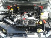
Check for boost leaks/vac leaks. Then stick it into test mode with the green plugs under the dash and clean out the BBOD and primary boost solenoid:
Solenoid box cleanout:
http://www.uklegacy.com/forums/index.php/topic/11043-code-66-and-boost-issueshow-to-clean-them-out/
Primary boost solenoid inside F/L guard:

-
OEM the outlet/vent hose from the boost solenoid connects to the plastic intake pipe pre turbo. Not the end of the world if it's venting to atmosphere, chances are you're going to need to run aftermarket boost control anyway.

-
In that pic:
Hose #11 - Straight to intake manifold.
Hose #15 - To the turbo/WG actuator T piece.
Hose #5 -- Bleeding back to the intake pipe
-
Pic/step # 5 above shows the lower turbo heat shield bolts that need to be removed while under the car.
Pic/step #16 shows all heat shields removed to unbolt the downpipe from the turbo.
Pic/step #20 shows the DP removed to undo the turbo bolts from above.
Only the 14mm uppipe support bracket bolts have a nut on the bottom. That can be accessed with a spanner from above the car, once the heat shields and downpipe have been removed completely:

-
1
-
-
If in any doubt at all. Always quality work and discounts for CS members. PM Ajay with any questions or for a quote::
http://www.clubsub.org.nz/forum/index.php?/topic/48694-subirex-automotive-limited/
Whiteline bars through evowrx:
http://www.clubsub.org.nz/forum/index.php?/topic/44326-whiteline-barsalk-northland/
Whiteline 99GF8 22mm adjustable part number BSR20XZ:
http://www.whiteline.com.au/product_detail4.php?part_number=BSR20XZ&sq=23369
Whiteline BSR20XZ installation guide:
http://www.whiteline.com.au/docs/install_guides/Z320.pdf
If you have the tools and you're keen to give it a go:
Nothing wrong with using a scissor jack, just slower that's all. But as GC8E2DD said, scissor jacks aren't as stable or strong as trolley jacks so best to lift one corner at a time. Rear left, then rear right. As long as it's on flat hard ground and you never put your body under the vehicle until it is sitting securely on axle stands (spare rims/blocks of wood).
When jacking a car to work under it's always best to chock the wheels that are staying on the ground, even with the car in gear and the handbrake on. Chock the wheels with a big rock or lump of wood, something that will stop the ground wheels rolling if anything goes wrong. For example an all wheel drive car with open differentials in gear with the handbrake on and the rear wheels being lifted off the ground for a swaybar swap, if the jack fails or tips over the car can still roll forwards or backwards.
Nothing wrong with using spare wheels as axle stands. As GC8E2DD said, jack the car up and slide the spare rims under the cars back wheels, then lower the car so it's sitting up on the rims. With both rear wheels level there is no tension on the swaybar and ARB links. Plus technically all suspension bushes and suspension links should always be tightened or torqued up with the vehicle suspension sitting at normal ride height. Not only for new part alignment and clearance checking, but for the suspension bushes to function as intended. A lot of suspension bushes these days are solid or made as one piece and do not have rotating parts. When the suspension articulates the rubbery section of the bush twists causing tension, then when the suspension goes back to normal ride height the bush goes back to neutral twist/neutral tension.
Not so critical with ball joint type rotating sway bar links. But picture a rigid type ARB link (anti roll bar link) with fixed solid bushes top and bottom. If torqued up with the suspension at full droop and then the vehicle is lowered to normal ride height. The fixed ARB link bushes will either tear apart and no longer be fixed, or twist and be under constant tension. Effecting both suspension movement (twist tension causing lift) and swaybar tension/behaviour (now favouring downward suspension movement and more resistant to upward suspension movement), plus it also shortens the life of the bushes.
-
2
-
-
My BH5B has a clutch switch, tied in with the starter system wiring. I have the my clutch switch bridged so that I can start the car without the clutch depressed.
Guessing yours has the same switch that might be playing up, check that the switch isn't loose or broken. Or try bridging it if it keeps playing up.
-
1
-
-
Added some more info to the OP.
Bore wall and stiffener thickness changes through the EJ207:
S20C -- 9.6mm Version 7/8 EJ207
T20C --- 9.6mm Version 9 EJ207
W20C - 13.2mm Version 10 EJ207
Version 10 STI block W20C beside the Version 7/8/9 S20C/T20C:

Then also some crankshaft differences:
12200AA210 - BE/BH EJ206/EJ208 ---------------- OEM cross drilled crank
12200AA240 - Version 5/6/7 STI EJ207/EJ205 -- OEM cross drilled crank
12200AA270 - Version 8/9 STI EJ207 GDBC ---- OEM double cross drilled and nitrated crank (better oiling and hardened - black colouring)
12200AA390 - Version 10 STI EJ207 GRB ------- OEM double cross drilled and nitrated crank (better oiling and hardened - black colouring)
JDM Version 5/6/7 STI EJ207 - cross drilled crankshaft:
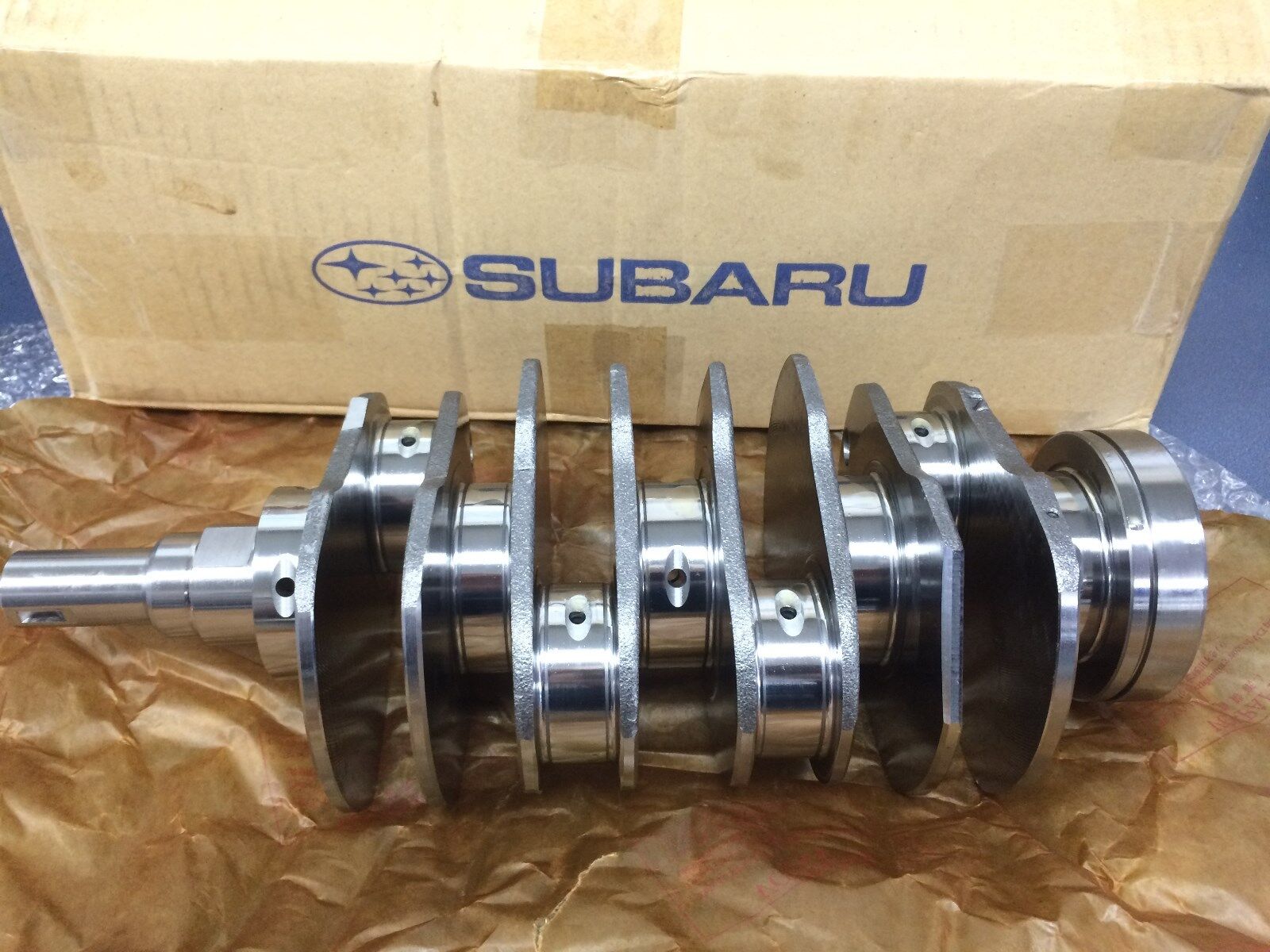
Version 8/9/10 STI EJ207 - double cross drilled and nitrated crankshaft:

-
1
-
-
Probably in excess of 350kw at the wheels. There's a few EJ207 crank differences to be aware of too:
12200AA210 - BE/BH EJ206/EJ208 ---------------- OEM cross drilled crank
12200AA240 - Version 5/6/7 STI EJ207/EJ205 -- OEM cross drilled crank
12200AA270 - Version 8/9 STI EJ207 GDBC ---- OEM double cross drilled and nitrated crank (better oiling and hardened - black colouring)
12200AA390 - Version 10 STI EJ207 GRB ------- OEM double cross drilled and nitrated crank (better oiling and hardened - black colouring)
JDM Version 5/6/7 STI EJ207 - cross drilled crankshaft:
Version 8/9/10 STI EJ207 - double cross drilled and nitrated crankshaft:
EJ207 block engine codes, head codes , piston and crank differences in here:
http://www.clubsub.org.nz/forum/index.php?/topic/41534-ej205ej207ej208-short-block-identification/
Here's a good write up on what the EJ stock internals can take:
http://www.superstreetonline.com/how-to/engine/impp-1103-subaru-ej-series-engine-tech/
-
If you find a swaybar for your vehicle in whiteline's list, down the bottom of the page it shows other models that the bar will fit:
http://www.whiteline.com.au/product_detail4.php?part_number=BSR49Z&sq=23258
For example the 20mm non-adjustable whiteline swaybar p/n BSR49 will fit:
BSR49Vehicle ApplicationsClick on your vehicle below for fitment details.SUBARU FORESTER SH INCL TURBO (9/2008-8/2013)
SUBARU FORESTER SJ INCL TURBO(9/2013-ON)
SUBARU IMPREZA GE SEDAN, GH HATCH EXCL WRX & STI(9/2007-8/2011)
SUBARU IMPREZA GJ SEDAN, GP HATCH EXCL WRX & STI(9/2011-3/2014)
SUBARU IMPREZA WRX GV SEDAN, GR HATCH(9/2007-8/2011)
SUBARU IMPREZA WRX GJ SEDAN, GP HATCH(9/2011-3/2014)
SUBARU IMPREZA STI GV HATCH(9/2007-8/2011)
SUBARU IMPREZA STI GJ SEDAN, GP HATCH(9/2011-2/2014)
SUBARU LEGACY BM SEDAN, BR WAGON INCL TURBO(9/2009-ON)
SUBARU LIBERTY BM SEDAN, BR WAGON INCL TURBO(9/2009-ON)
SUBARU OUTBACK BR INCL TURBO(9/2009-ON)
-
Are you running an aftermarket venting blow off valve?
-
This is a merge of posts from my garage thread. Covering my BH5 GTB 5MT centre differential change to a Version 8 WRX centre diff:
http://www.clubsub.org.nz/forum/index.php?/topic/40292-rosssubs-gtb/&page=4
Started ripping the BH centre diff out this evening. After driving at 100kph for a while, then trying a tight turn it's locking up pretty bad. Car jerks forward violently as though all the CV's are stuffed. Also making it under steer easily at any speed when the centre diff's hot/binding.
Jacked up and GB oil drained:

Driveshaft out:

GB supported with a jack:

GB cross member removed

Here's the shifter linkages at the rear of the GB:

Shifter linkage and stabiliser unbolted:

Locking slide pins removed from shifter linkage knucle:

After removing both locking pins (inner/outer) the shifter linkage knuckle will come off:

Exhaust hanger bracket and transfer case rear cover unbolted:

Rear cover (extension case) ready to come off:

Using a flat head screwdriver and hammer to separate the transfer case/rear cover:

Worked apart nice and evenly:

Centre diff and driven gear coming out:

Removed:

Driven gear shaft and centre diff slid out of rear cover:

Transfer drive gear removed from centre diff:

Gasket surfaces all cleaned up and ready for the replacement diff to arrive:

Here's the replacement centre diff, it's from a Version 8 WRX.
BH5B (TZ254) - Version 8 WRX (DA230)

BH5 - V7 WRX

New diff installed into rear casing then lubricated:

3-4mm bead of gasket silicone on the transfer case:

New center diff/rear casing installed and torqued to 40 Nm(29.7 ft-lb), then exhaust hanger bracket back on:

Shifter linkage knuckle and stay back on:

GB crossmember and driveshaft back in:

Just topping the oil up (3.5L), then it's time to set the new EBC up.


Here's a thread by Gazzy2000 covering swapping to an earlier phase 1 WRX/STI centre diff, centre casing and rear casing:
Then DRFVDR's centre diff locking for RWD how to thread:
-
Here's all five original 'Rex On Rails' documents from Whiteline:
Part 1 - WRX standard suspension and wheel alignment adjustments:
http://www.whiteline.com.au/articles/AS_Rex_on_rails_1.pdf
Part 2 - WRX Rear sway bar upgrade:
http://www.whiteline.com.au/articles/AS_Rex_on_rails_2.pdf
Part 3 - WRX Anti lift/castor kit:
http://www.whiteline.com.au/articles/AS_Rex_on_rails_3.pdf
Part 4 - WRX Front sway bar upgrade:
http://www.whiteline.com.au/articles/AS_Rex_on_rails_4.pdf
Part 5 - WRX Adjustable rear camber kit:
-
$275-$325
http://www.whiteline.com.au/vehicle_swaybars.php
Wheel alignment can have a big effect too. There's some good write up's on improving WRX handling at the bottom of this thread:
-
1
-
-
I mounted a 1KG dry powder fire extinguisher in the Legacy a few weeks back. Thought I'd make a thread with some pic's, details and info. Initially installing a daily driver single strap extinguisher that was a gift, then changing to a double metal strap holder with uprated bolts suitable for track use. I've broken this thread into two sections:
Fire Extinguisher Install - Part 1 - Daily Driver
Fire Extinguisher Install - Part 2 - Track Use
Part 1 - Daily Driver Extinguisher Install
I stopped in at a local engineering workshop and brought a 500mm length of alloy flat bar, 25x4.5mm for $4.50:

Planning to mount the extinguisher to a bracket fitted between the front passenger seat rails, I've bent the alloy bar for a good fit using the corner of a workbench and a G-clamp:

Bent bar dimensions:

I sat the new bracket in place and marked the bolt hole centres:

Then centre punched to stop the drill wandering when starting drilling:

First drilled to 6mm:

Then drilled to 10mm:

I've trimmed the brackets inside lower corner to stop it digging into the carpet:

Bracket trail fit:

After working out exactly where I wanted the extinguisher to sit:

I've marked the extinguisher mount bolt holes onto the new bracket:

Then after centre punching again, drilled two 6mm holes:

Extinguisher mount then bolted to the new bracket, using 12mm long M6 gutter/panel bolts:


I unbolted the mount again, scratched the alloy plate up with sandpaper and then primed it:

Then a few coats of black enamel:

New daily driver fire extinguisher mounting bracket installed:

Extinguisher in:

Seat adjustment still working as normal:

Part 2 - Track/Club Sport Extinguisher Install
Wanting the extinguisher install to be suitable for club sport/track use I've checked vehicle handheld extinguisher requirements:
Motor Sport New Zealand - Appendix 2/Schedule A - Fire Extinguishers:
http://www.motorsport.org.nz/content/appendix-two-schedule-0
CAMS - Confederation of Australian Motor Sport - Schedule H - Fire Extinguishers:
http://www.cams.com.au/motor-sport/regulations/cams-manual/general-requirements
But you can also check in with your local event organiser:
http://www.christchurchtrackdays.com/event-schedule/vehicle-requirements/
I stopped into Butler Auto Mart and brought a 1KG Chubb dry powder extinguisher with a twin metal strap bracket for $40, much smaller than the Orca 1KG original.

Here's a very similar option from Mitre10 Mega, a Quell 1KG dry powder with twin metal straps (CAMS approved) for $35:
I then went to Blacks Fasteners and got a selection of (minimum ISO 8.8) M6 16mm bolts, washers and nyloc nuts. For a grand total of $2.00. The two bigger washers are panel washers, used when fitting an extinguisher to a body panel:

I removed the daily driver/single strap extinguisher mount, then positioned and marked the new twin strap bracket bolt holes:


Only needing to drill one new 6mm hole:

After drilling, then sanding and touching up the black paint.

The new extinguisher mount was bolted to the seat rail bracket using the ISO 8.8 M6 bolts, washers and nyloc nuts:


New twin strap extinguisher mounting bracket bolted to the seat rails:

New 1KG fire extinguisher installed and ready for event scrutineering:

Seat adjusting lever unobstructed:


-
7
-
-
Give the idle air control valve a good clean out with carby cleaner. If it only ever does it when it's cold, or only when it's warm it could be a faulty coolant temp sensor. If it's always low or erratic then it's more likely a vacuum leak somewhere.
Here's some diagnosis info from a recent thread with similar problems:
On 18/08/2016 at 10:37 PM, Rosssub said:Sensor's like the coolant temp sensor can effect idle, warm signal when the engine is cold. But more likely a vac leak or a sticky idle control valve, so best to rule them out first. You will see some pic's of the idle control valve in borland667's garage thread linked below. Remove it from the manifold and give it a good clean out with carby cleaner:
http://www.clubsub.org.nz/forum/index.php?/topic/45394-wrx-sti-v3-restoration-project/&page=4
To check for vacuum/boost leaks. With the car idling you can spray ether (starting fluid) around any possible leak spots. If any fluid gets sucked in the idle will change instantly.
Or block the intake off at the AFM somehow:

Then pump 10-15 psi into the intake manifold with an air compressor. Any leaks will hiss and be obvious.

-
1
-
-
Fuel pump relay seen in here:
http://www.clubsub.org.nz/forum/index.php?/topic/45370-fuel-pressure/
Relay and wiring in here:
http://www.clubsub.org.nz/forum/index.php?/topic/48315-fuel-pump-kill-switch-install/#comment-603325
The mongoose have options for the immobiliser circuits so will depend how it was installed. But the FP should definitely be priming with ignition on.
-
2
-
-
53 Antenna 53 Anti-Quick Operation Mode 53 Communication Error (Time Over) 53 EGI Control Module EEPROM 53 IMM Circuit Failure (Except Antenna Circuit) 53 IMM Control Module EEPROM 53 Key Communication Failure 53 Reference Code Incompatibility 53 Use of Unregistered Key 54 Air Intake System 55 EGR Valve Lift Sensor 56 EGR System 57 Canister Control System 58 Air Control System 61 Air Suction Control Solenoid Valve 62 Exhaust Manifold Valve Negative Pressure Control Solenoid 64 Relief Valve Control Solenoid Valve 1 64 Relief Valve Control Solenoid Valve 2 65 Differential Pressure Sensor 66 Twin Turbocharger System(H) 66 Twin Turbocharger System(S) 66 Twin Turbocharger System(T) 66 Two Stage Twin Turbocharger System 67 Exhaust Manifold Valve Positive Pressure Control Solenoid 68 Turbocharging Pressure Control Output Signal #2 71 Shift Solenoid Valve 72 Shift Solenoid #2 Circuit 73 Low Clutch Timing Solenoid Circuit 74 Brake Clutch Timing Solenoid Circuit Malfunction 75 Line Pressure Duty Solenoid Circuit 76 Brake Clutch Pressure Duty Solenoid Circuit Malfunction 77 Lock-Up Duty Solenoid Circuit 78 Tiptronic Solenoid System 79 Transfer Clutch Duty Solenoid Circuit 81 Torque Up Control Valve 85 Charger System Circuit Malfunction 86 CAN (Communication System) 87 Variable Induction Solenoid Valve Circuit Malfunction 88 Fuel Pump Circuit Malfunction 89 VVT Systems (L) 89 VVT Systems (R) 91 TCS Relief Valve 92 Electrical Generation Control Signal Circuit Malfunction 93 Vehicle Speed Sensor #1 Circuit 94 Lateral G Sensor Signal Circuit Malfunction -
2
-
 1
1
-
-
Got the rotors from Edge Parts & Performance Christchurch:
-
Lowering the CR without tuning will cause the engine to loose torque and efficiency. Adding more boost (if you can) may compensate slightly while on boost, but the timing will be off throughout all engine loads. Start up, idle, cruise, medium load and even throttle response will all be effected. Less power, less fuel efficient and less off boost driveability.
Unfortunately the conversion you're taking on is not as simple as installing an adapter loom, AFM and ECU. The 4 plug ECU grounds most engine sensor shields and some grounds through the ECU itself. The newer 3 plug ECU grounds these sensors/shields directly to the engine block. You will need to alter the earth/shield wiring and IIRC also run a dedicated ground for the AFM. All the 4 plug to 3 plug conversion wiring documentation is covered in here:
Then more info in here:
http://www.clubsub.org.nz/forum/index.php?/topic/43394-ecu-repinswap/
If using a V1/2 WRX ECU you would need to change the TPS. The earlier TPS output voltages are reversed and it has an idle switch with an extra wire to the ECU.
-
Partsouq for comparison, the OEM BE/BH/GDB coil FK0140 p/n 22433AA421 is $109.73nzd:
-
On 26/08/2016 at 2:56 PM, legacygt95 said:
I found a 2S ECU out of a standard WRX version 3 which I am getting an adapter made to plug and play and I was told that the version 3/4 run blue afm and greys so could anyone clear this up?
As above the JDM 2S EJ20G Version 3 WRX GF8 (wagon) runs a purple AFM and grey injectors, with CR at 9.0:1.
On 30/08/2016 at 1:13 PM, legacygt95 said:I have acquired a 2s ECU along with a adapter so connect the 4 plug into the 3 plug 2s ECU. But apparently the compression ratio on the ej20g it came from has compression of 8:1 and the ej20h I have now has compression 9:1 so would there be an issue? It's single turbo converted with a VF29 but don't know if the ecu would be agressive enough as its non Sti
You'll see in the chart I posted above that your EJ20H 95GT (OEM blue AFM) runs CR at 8.5:1. Some have had ok results with a slightly different CR engine-ECU, some have not. The WRX 2S ECU is set up to run a TD04, so changing to a VF29 you will need aftermarket boost control, MBC or EBC. IIRC you will also need to change your TPS, MAP sensor and ignition coil wiring.
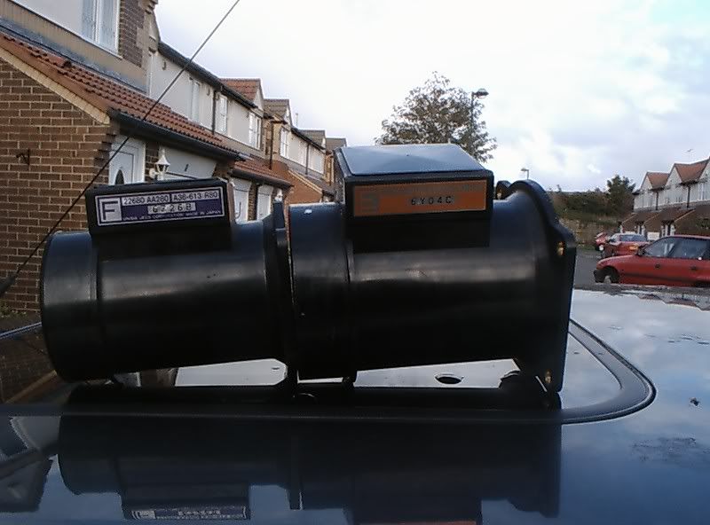
After comparing JDM AFM loom plug pics, part numbers, engine wiring diagrams and ECU pinouts the above ECU/AFM information is correct.
The Version 1/2 WRX/STI EJ20G and BD/BG5A EJ20H with a four plug ECU use a 5 pin AFM. The JDM 5 pin AFM options are blue and green. (some models only use 4/5 wires)
22680AA200 Blue Label --- 5 pin AFM loom plug - EJ20H
22680AA160 Green Label - 5 pin AFM loom plug - EJ20G
The Version 3/4 WRX/STI and BD/BG5B-C with a three plug ECU (auto single plug ECU), use a 3 pin AFM. The JDM 3 pin AFM options are purple and orange.
22680AA280 Purple Label -- 3 pin AFM loom plug - V3/4 WRX wagon EJ20G & BG5B-C EJ20H
22680AA271 Orange Label - 3 pin AFM loom plug - V3/4 WRX/STI EJ20K & BG5B-C EJ20R
Although the 5 wire blue/green and 3 wire purple/orange AFM could probably be interchanged/rewired, they have different housing pipe diameters, so will have different airflow/voltages. Below is the JDM Version 3 2S EJ20G WRX purple AFM, beside a JDM Version 3 1S EJ20K WRX orange AFM:
For the best results fit a 3 plug 6S or 75 V3/4 STI ECU, yellow injectors and an orange AFM. The same amount of work for a stronger engine, more air flow, more fuel, more boost and a higher boost cut.
-
1
-
-
Who's Online 1 Member, 0 Anonymous, 89 Guests (See full list)
Changing BE/BH Fuel Pump
in Legacy & Outback
Posted
Nah the AEM 50-1200 is too big at 124mm, same as the DW200 and Walbro. Should be listed above.