


Gripless
-
Posts
1,968 -
Joined
-
Last visited
-
Days Won
104
Content Type
Profiles
Forums
Events
Store
Posts posted by Gripless
-
-
Ok so searching for some parts I found other random items, the cover I wanted but he other MAF blank plate I couldn’t find
center console sliding cover $24 shipped
https://www.aliexpress.com/item/1005005912313226.html
alternator pulley dress up cover $50https://www.aliexpress.com/item/1005005523118969.html
brake booster stop $60https://www.aliexpress.com/item/1005005666874166.html
short gear shift $55
https://www.aliexpress.com/item/1005002466624862.html
cam toolshttps://www.aliexpress.com/item/1005002906222456.html
-
 1
1
-
-
You pretty much have to swap the auto brake pedal to manual one to fit clutch pedal for some or all the below unless you can go to LVVTA certification place and they say it’s all ok in writing.
1) it’s too close together for safe operation or fouls
2) it shares bolts or bracket with brake pedal
3) WOF will likely flag pedal of car is not automatic on next visit
4) drive shafts are swapped so while OEM are not original
5) your insurance maybe denied after an accident and they see the pedal
6) firewall is structural and weakens brake pedal mounts
7) firewall needs to be sealed so cutting and putting new holes is also red flag
8) some cars the firewall isn’t the same for auto and has less reinforcement
Do NOT try and bypass or creatively interpret LVVTA rules. Always ask and get it in writing every time.Also any future plans or mods that go to LVVTA may cause issues.
i certed my swap a few year later when did coilovers etc. mine was pretty easy as had all OEM parts and even a template for drilling the clutch master.
-
 2
2
-
-
2 hours ago, Andy_Mac said:
Hasn't it always needed a cert because of the brake pedal swap? It has been that way for at least as long as I can rememberNope was free swap for decades

-
1
-
-
The ‘eventually’ part says sell it.
If you don’t have the funds to do it now then sell before it becomes a money pit.
Also doesn’t manual conversion require cert etc now, was way easier before.
-
1
-
-
Nope was pretty good inside, just shims and a few synchros. Seals as well but no bearings or costly things. Parts from partsouq are -$250 shipped.
Also confirmed the helical front lsd which I don’t think was in the original box.
-
1
-
-
Well gearbox rebuilt and setup correctly.
holly s*** what a difference.
Now no gear shifter slop as it had previously even with all rubber bushings replaced.no whine on lift off either
-
1
-
-
Perrin and other brands say 08-20 for top mounts
What do you need?
-
13 hours ago, Andy_Mac said:
dunno about anything on this side of the world but the US had a heap with uppipe cats. Only ever a single scroll thing but a major headache for them as they had a tendency to break down and kill turbos.Wow that’s a horrid idea.
California does have some crazy emission rules.
-
Most cars only have 2
Anything pre turbo would kill exhaust pulses so unlikely one in up pipe.
-
That’s got to be a s*** time.
hHeard the same with other brands saying things verbally but won’t commit to writing it so LVVTA pretty much has its hands tied.
only the coder of the device would actually know how it works and what would through it all out.
-
Sounds like anything that moves or repositions a sensor will not be legal or even able to be certified.
So things like wide body kits, grills even mirror that have sensors cannot be moved or get get in the sensors way.
Parking sensor should be ok as long as they aren’t used by other systems. Though not sure on how you prove this.
eg
Lane assist
accident warning system
radar cruise control
Cars mostly other than wide body likely ok.
Utes and trucks that fit large bull bars, winches, longer tray or canopies could be caught out. Since they are the ones historically that get the modifications and are starting to be sold with all the electronic aids.
-
2
-
-
5k in 2014 was normal rebuild price with just rings and bearings.
there’s a good chunk of cost pulling and refitting motor that won’t be in forged build price. Just assembly would be 7k in labour.
You can also waste time and cost measuring up and washing all the old parts on rebuilds. Most places will still strip the bottom end for inspection as you already know the valves hit the pistons.
forged is 3k for rods and pistons which you can add to any build.
For forged you also spending 7k more for the same power unless you plan on more power. Then you really want ported heads on the list so that adds $$$
What are you calling a crate motor? Even secondhand unchecked ones are 7k range
-
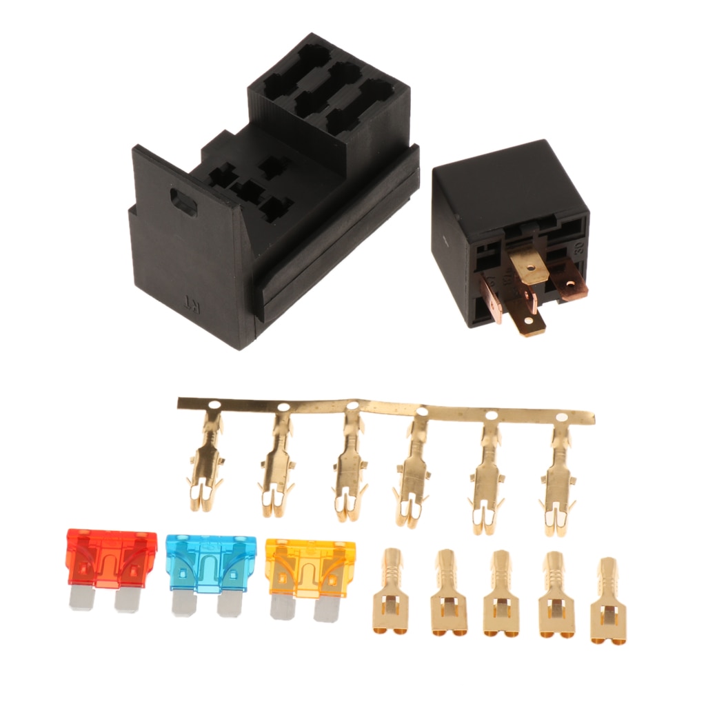
This would work 3 fuses, and flasher relays do come in the same footprint as these common relays just dont need all 5 connections. They run 2-4 depending on type.
-
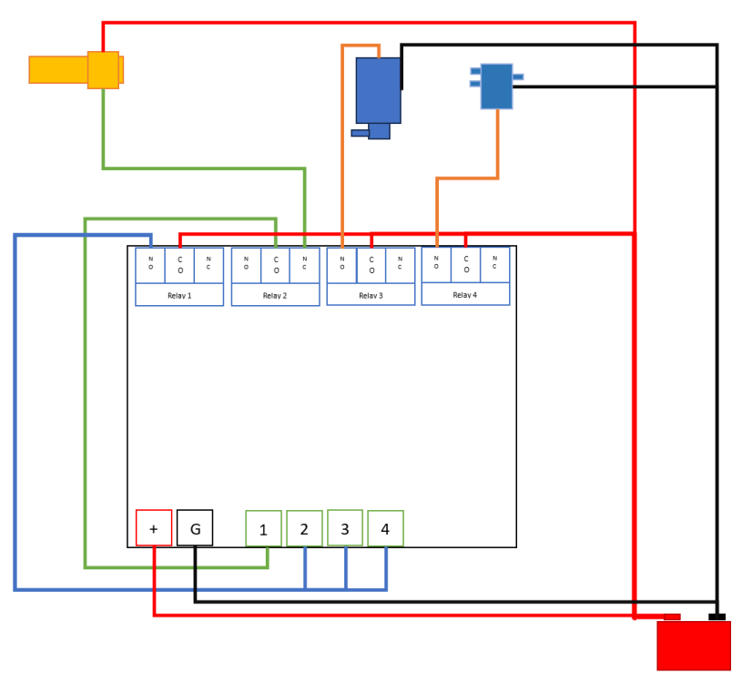
MSword is slightly better than MSpaint
Things in drawing are:
Temperature switch, pump, solenoid.
4 Channel relay timer
Battery
Piping not shown
I'd add:
an indicator flasher relay between the solenoid and relay 4 NO connection for best efficiency and water savings.
Also fuses should go between battery and relay common for relay 1,3,4 based on cable and device size.
Heat-shrink and terminal fittings rather than bare wires etc
Solenoid can either
sit directly after pump and recirculate water back before pump
or
Sit between nozzles (or nozzle pairs if you run 4) so it alternates left/right or top/bottom for longer evaporation time
-
Pump depends on the jets you use:
windscreen or headlight washers are lower pressure
mist and irrigation are higher pressure
Hose needs to fit and hold pressure of:
pump
nozzles
Tee pieces
one way valve. Needed for washer and high flow irrigation nozzles. Irrigation no drip while not one way do the same.
-
True cost is not low but no fab work is huge saving.
My EFR is nearly twice the price it was 4 years ago.
Does it fit LHD… no idea.
Also not twin scroll so 2.5L only unless you want to swap back for rumble with isn’t uncommon.
-
1
-
-
5 hours ago, Andy_Mac said:
This may be simple for you in your field but this seems way too techy for me.
ECU control is nice but could you not have some form of super basic controller with a contact thermometer on the backside of the intercooler outlet to let you know if temp is getting up and then have it run for a max amount of time and then shut offYes the basic one based on relays in that fuse box could be attached to a temp switch rather than a button.
EDIT:
Ok look at pretty diagram a few posts below for what this loooooog text looks like.
orthere are 4 relay timers that would stop the system running constantly until temp is low.
https://www.aliexpress.com/item/4000273267216.html
https://www.aliexpress.com/item/1005004681220191.html
Idea would be to have temperature switch trigger relays eg
connections
Unit power to 12v and ground.
temperature sensor connected to NC output of relay 2, and then relay 2 common to input 1
relay 1 NO output is connected to input 2,3,4
relay 3 NO output is pump
relay 4 NO output is solenoid if you want that
relay 1,3,4 common are 12v battery via fuse or fuses see below.
Working
Temp switch triggers input 1 and then that would trigger input2,3,4
relay 2 then disconnects input 1 since NC becomes open for a time so waits for water to have effect, otherwise it runs nonstop until temp drops.
relay 3 runs pump
relay 4 opens solenoid to allow water to jets or just does nothing.
fuses
Relay 1 only drives other relays, and relay 4 is solenoid so 3w. Pump is whatever wattage but likely higher than others.
timers
1 just 1 second as just sets off others
2 time to wait before checking temp sensor again
3 pump run time should be shorter than timer 2
4 solenoid depending on how connected to pump or ignored.
would be best to also add switch between temp switch (or unit power) to cabin so you can choose if the system is on or off.
Just have to find a temperature switch in the range you want. They are common items for HVAC and for thermo fans in cars so plenty to choose from.
just for anyone in future. Relays with 5 pins2 pins are to coil that switches the below.
NO is relay that tab that is normally and open circuit or disconnect until relay is active.
NC is opposite to NO, so circuit is connected until relay triggered.
Common is what NO and NC connect to. Can be 12v or ground or whatever you connect to it.
-
Very nice.
Used plenty of windscreen washers in bumpers before but those save the pissing about with a needle/pin to rotate the jet up and almost closed.
Even on lower lip their low profile still looks good so could run 4 if you wanted.
Nothing stopping reusing the headlight popup nozzles either so they would lower from top down towards middle of intercooler.
-
1
-
-
-
Needs more work, but initial syntax in single byte messages
missing
- Startup code to announce IC spray unit is working and ready
- A way to return zone count
- Some operational error for water level and flow rate returned values (eg count over what time period, units to be converted to/from)
-
possibly a few generic setup codes and hardware buttons.
- Way to set canbus ID externally but cant exactly have 11 switches to set it.
- send packet with configured ID when a button on the board pressed so you can see the ID in a capture.
Requests codes -> possible replies
Diagnostic codes start with 0
10###### External Hardware
Used to test physical connections eg cycle would create audible clicking from a relay
11###### Internal ESP32 Hardware
Mostly useless but can log if think there are issues

Operational codes start with 0
00###### Manual triggered

01###### Automatic (must pass canbus ID for temp as next packet)

Anyone feel free to copy this and build your own version for non commercial use.
-
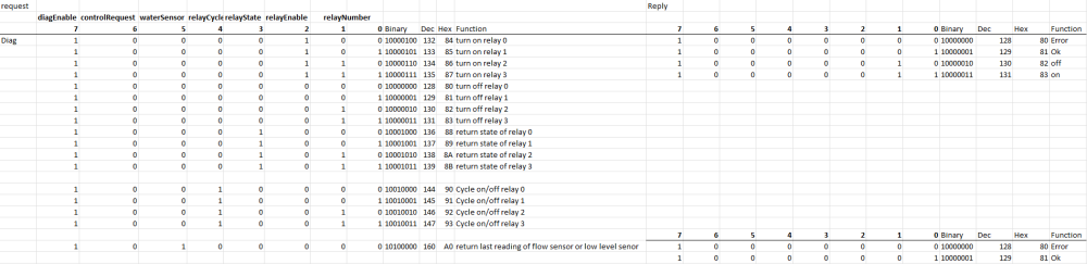
Have worked out canbus code byte values.
Only thing it needs to have hard coded is ID and the ID to listen for the intake air temp for auto mode.
Auto to intake temp needs high and low byte as second byte would be target temp.
Relay cycling has to be preset number or needs high and low bytes so can set default to 10. Since the idea is just to get it to click so you can tell if relay is dead.
4 relays can do
Any 1 of 4 zones but spray is on/off by pump
advatange is more zones,
disadvantage spray comes on slow as pump builds pressure at start and drops at end so wastes a small amount of water each time. No delay between zone spray, just one after the other.
or
Any 1 of 3 zones and pulsed by solenoid that return water to tank or before pump until need.
disadvantage less zones. Pump still runs full time.advantage build up and cut off are instant from solenoid so zero drip waste. Can program in more delay between zones so has longer evaporation time. More cooling less water.
esp32 can have wifi updates to code so could be DIY setup even on car without access to usb or serial connector.
Could preset the canbus ID to a default ID in a known range based on ecu like link, Emtron motec etc.-
1
-
-
For those with canbus aftermarket ecu
https://www.aliexpress.com/item/1005004213766448.html
and any canbus module
https://www.aliexpress.com/item/1005003450161614.html
Or
https://www.aliexpress.com/item/32757441080.html
esp32 has canbus controller built in so only need the transceiver that does the physical connection. Arduino needs a controller like mcp2515 plus transceiver.
Could be programmed for different operations modes.
ecu sends time to run in secondsunit automatically runs cycles until time is up
ecu sends on
unit runs single cycle
Ecu sends start and stop
unit runs until stop received
ecu send target intake temp
unkt runs, then waits 3 second, requests temp, repeats until temp under target or stops after 10 cycles
Ecu sends status requestunit send running, idle, even water low if senor hooked up. Could be flow meter inline rather than water sensor in tank. If last run had no flow assume water low/empty.
Diag options if unit is idle ecu can request
relay # on for X seconds
relay # cycle on of at x hz for x seconds
Relay # current state. Use with above or should be off
Water level low sensor current state
Water flow meter current reading. Need to turn on or cycle relay for pump using above.
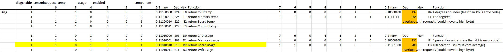
CPU usage
Memory usage
CPU temp
Board temp
Even Wifi status if those are used. could run wifi AP with webpage showing connections and status of each part of unit and connected pump.
canbus dumb version have to trigger each relay.More suited to meth or extra pump control etc.
https://www.aliexpress.com/item/1005005510819149.html
Alternative dumb single wire for button. You trigger input1 that runs 10 seconds triggers input2 input3 which run pump and solenoids in pattern as required.single press with can run a single cycle.
input4 could run different or longer pattern. Or turn in intercooler fan when handbrake is on.
-
1
-
-
https://www.trademe.co.nz/a/motors/car-parts-accessories/performance/electronics/listing/4258707187
option for tidy package.can get timer and flasher relays in standard relay size packages.
fuse for pump, solenoids and input even water level sensor would all fit.
-
4 minutes ago, lowandy said:
Look into V8/9 STI Long runner manifold. Doesnt use the TGVs which should help unless you need to keep the TGVs for whatever reason. Are you in Auckland?
Yeah, but finding one is not easy and would have to swap throttle body and get new map sensor.
throttlebody should be fine to use the 2.5 NA which is 70mm but same outer size.
7/8 map sensor isn’t on throttlebody so would need new sensor.


-
Who's Online 1 Member, 0 Anonymous, 83 Guests (See full list)
What have you done to your car today?
in General Vehicle Discussion
Posted
That would clunk pretty loudly