


telemekas
-
Posts
214 -
Joined
-
Last visited
Content Type
Profiles
Forums
Events
Store
Posts posted by telemekas
-
-
"no one else has done this around the poluted planet we live on unless someone can direct me to them?"
Mr Turbo does modify VF CHRAs
-
The two ports on the ECV actuator have different functions.
The top port (pretransition postive pressure only) will only partially open the valve at high engine loads and boost.
Therefore bleeds exhaust like a wastegate and aids secondary prespool. A smoothing effect during hard acceleration runs or climbs.
The bottom port (post transition negative pressure (vacuum) only) will open the valve fully at the predetermined RPM (transition point) set by the ECU regardless of what is happening with the top port.
The sequential system will still operate without the top port being active.
-
I have done a slightly different ECV modification:
2.5"( 63mm) butterfly valve located low down in the 2nd turbo dump pipe.Vacuum operated via No:6 port.
A further extension to this:
The ICV has also been replaced with a 50mm passive one way check valve.
This has improved timing of the valves and allowed removal of the supercharger pressure relief valve.
-
Connect the the Black set and the Green for ECU reset
http://homepages.ihug.co.nz/~ccgrant/celcheck.htm
Connect the Greens only for solenoid/fan/valve function check
-
The VF14 has the unique 5700 turbine wheel (39mm exducer and larger tip height) and is nested in the unique secondary P16 turbine housing (all the other 2nd turbine housings are P18)
The VF25/VF26 and VF27 use the 8 blade 6200 wheel, while the other TT turbos use 9 blade 4600 wheel.(all with 36mm exducer)
The non BB VJ32 uses a 'similar' dimension wheel (6800) to the VF14 but has 11 blades compared to the VF14s 9 blades.
-
Yes you have to reset from scratch unfortunately, if you want to change from KPA to PSI
-
"Or if someone could tell me how to change it from kPa to Psi ?"
Initial set-up page 29 of manual.
-
-
-
Straight swap physically.
The VF18 has a slightly larger Compressor Wheel Trim than the VF20
-
A quick check of the ECV duty solenoid. This would be active as you descibed
"second turbo begins to come in.. but only in 4th and 5th and once so far in 3rd"
This solenoid can be isolated for a check. Disconnect the positive pressure line No: 5 from the top port of the very large ECV actuator on the drivers side engine bay.There will be a short step up hose.Plug the hose only.Test drive the car
-
Will this work on my 01 Legacy GTB revD etune
Could i successfully retard timing with this if it fits?
Ta
You will need the Subaru Select Monitor (FreeSSM) program.
This will enable you to:
Reset ECU
Check/Clear DTCs
Adjust timing up to +/- 5 degrees on the fly via the ROM and is not a reflash therefore a reset will clear the adjustment.
Idle RPM
4EAT adjustments
This will work with any cable that has K/L or KK/L interfaces and Tactrix 1.2 or 1.3 but not 2.0 as yet.
http://prdownload.berlios.de/freessm/FreeSSM-1.2.5-windows-qt4-installer.exe
-
Hi Guys im new to this site and subarus in general, so please be kind. lol
I have a 01 gtb tt e tune that is totally standard apart from a sti genome boost gauge and controller, I always put in super unleaded, and since i have had it i have had pinking or knocking issues and pre detonation boost issues, I chucked it into sub lab in whangarei and had the ignition timing backed off by 3 or 0.3 degrees (not sure which but whichever sounds right that'll be it) after i had this done it seemed to be fine for a couple of weeks but now the problems seemed to have come back with avengance, especially going uphill, the engine starts pinking its tits off from low revs and from less than 0.5 bar of boost, it will usually boost fine all the way to 1 bar but you can feel the engine holding back sometimes, and then some times the pre detonation controller kicks in and knocks boost down to 0.5 bar and it won't go over that for a while.
Also fuel consumption has gone through the roof since the problem has started to get worse, my assumption would be the ecu dumping fuel when its pinking to compensate, any ideas guys on how to solve this ? I do have a theroy that maybe when sublab backed off the ignition timing that maybe the ecu somehow reset the timing back to factory setting somehow, but i never got a flat battery or anything to suggest that, but maybe thats a common thing ???????
These cars are tuned to use 100 octane anything less will cause some problems.
Use Subaru upper engine cleaner to clear carbon deposites.
Have SubLab check trouble codes,reset ECU and adjust ignition timing by -5 degrees.
(If you have a Laptop and the correct cable you can do this yourself, using SSM program)
-
Hypothetically if you could swap all the turbine housing directly.
P18+VF37=VF30
P25+VF30=VF37
P25+VF22=Twinscroll-VF22
P25+VF23/24/28/29=twinscroll version of each or the same turbo x 4
-
No rebuild kits for these BB turbos.
-
Do you still have the old VF31?
Then you can directly replace the broken CHRA using one from a VF32.
The VF31 and VF32 use the same wheel sets.
-
The VF14 the first secondary turbo is unique with its P16 turbine compared to all the others with P18.However it is also the only turbo to use the 5700 turbine wheel compared to the 4600 used by all the other turbos (except the VF25/26/27 they use the 6200).The 5700 wheel has a larger tip height and approx 39mm exducer compared to the 4600 wheel with a smaller tip and approx 36mm exducer.
So even though it has P16 with its larger 'trim' wheel, acts like P18.
-
Standard IHI RHF4 rebuild kit check EBay
Alternative is to generate a BB VF26. Pick up a secondhand VF27 then swap over the compressor cover and turbine housing from the VF26.
-
That depends on the combination of compressor wheel/turbine wheel/turbine A/R used.
What have you used?
-
Yes the 2.5L was quick add on.
In which case I would run some heavy wheeled TD04s or high flowed VF14 CHRAs
-
Does anyone know much about these?
It seems car was fitted with a complete SYMS exhaust system in Japaland including the headers. Now from what researched and from looking at my car the manifold is designed to make the turbos run in parallel rather than sequential due to the lack of a ECV on the secondary up-pipe.
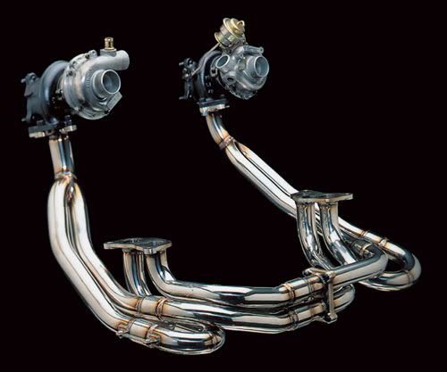
Now the obvious flaw with this is the ECU doesnt know whats going on anymore. Ive found on the SYMS website that it states the differential pressure sensor needs to be removed as its not doing anything anymore.
" EX s for our Regas***suintabo Manihoruto specifications are ordered always turning the two turbo.
On the relationship genuine Manihoruto s installed in the EX, you must remove the couplers and the differential pressure sensor. (Not a safety issue)
Thus, the check engine light will be lit at all times. "
Seems a bit rangi by japanese standards to go cutting out sensors ???
No need to remove Pressure Differential Sensor hose No 22 connects to No 5 on Solenoid Box or T off with No 2 or No 3.
Headers make it a parallel set up and split twin scroll. However the turbos are not totally equal (different size exhaust A/R or P and turbo type BB vs Sleeve)
If you have VF27 secondary turbo it has P18 and BB. The primary is VF25 (P12) or VF26 (P14) and are Sleeve bearing. All three turbos have the same size wheel sets.
Total separation of the exhaust gas to each turbo as no cross pipe (1 Litre each). Order of exhaust pulses primary/2nd/primary/2nd.
The VF27 would be difficult to over boost with 1 Litre and P18. Plus these turbos run high flow 8 blade exhaust wheels.
If you did want a wastegate for the VF27 the only one available that would fit is from a VF17.
These headers were really designed for the older turbo combinatios VF16/VF17, VF18/VF19, VF20/VF21 and PE1016F/PE1018F where the only difference between each in the set was the turbine A/R (P16/P18) "almost equal".
The real restriction with these headers is the secondary turbine flange will fit only P18. I would swap it for a primary flange and then you could use any of the primary turbine housing.
These are P11,P12,P14 and P16 with waste gates. So you could set up truly equal boost controlled turbos.
A 2.5L engine would be even better.
-
Diagram is for sequential set-up.
-
-
-
Who's Online 1 Member, 0 Anonymous, 147 Guests (See full list)
ceramic bearings in vf series turbos
in Engine Related
Posted
Yes I have read what he does!
"i on the other hand keep everthing OEM"
The above was not conveyed specifically in your first post.
My mistake.
My apologies.