
Rosssub
-
Posts
3,947 -
Joined
-
Last visited
-
Days Won
2
Content Type
Profiles
Forums
Events
Store
Posts posted by Rosssub
-
-
Can you hear the fuel pump priming? A bad fuel pump will not stop the engine from cranking (turning over).
Does it have spark? Any CEL?
-
 1
1
-
-
Welcome to CS. If the primary turbo is ok and pressure on the WG actuator changes the noise. it could be the WG flapper button loose and vibrating only at certain RPM. Try grabbing the WG actuator arm and lifting it, to see if the WG is closed tight or sitting slightly open.
Or could be a missed turbo/up pipe mounting bolt that's rattling at certain RPM, there's a few easily missed bolts under the primary turbo.
-
Thanks Clint.
-
Hard to say without seeing a pic of your engine due to the unknown single turbo conversion, also depends what has been changed inside the BBOD.
You have possibly disconnected vacuum to the MAP, FPR or left a hose venting (vacuum leak). All hoses need to be connected and not venting.
OEM hose #11 goes to the MAP sensor and is perfect to T into, but the original hose must stay connected:
-
The WRXs that ran greys and a purple AFM were the non-STi wagons and used a 2S ECU.
Note the compression ratio on these was higher at 9:0:1.
Spot on Tim, also:
Version 3 WRX:
Sedan EJ20K ran a 1S ECU, orange, yellows, 8.0:1CR vf22
Wagon EJ20G ran a 2S ECU, purple, greys, 9.0:1CR TD04
Auto -- EJ20G ran a 3S ECU, purple, greys, 9.0:1CR TD04
STI ---- EJ20K ran a 6S ECU, orange, yellows, 8.0:1CR VF23 (P20) -- (camshaft profile change v3/4 STI)
Version 4 WRX:
Sedan EJ20K ran a 88 ECU, orange, yellows, 8.0:1CR VF24 (VF23/P18)
Wagon EJ20G ran a 89 ECU, purple, greys, 9.0:1CR TD04 (89/8Z ECU p/n 22611AD730)
Auto -- EJ20G ran a 8Z ECU, purple, greys, 9.0:1CR TD04 (89/8Z ECU p/n 22611AD730)
STI ---- EJ20K ran a 75 ECU, orange, yellows, 8.0:1CR VF24 -- (camshaft profile change V3/4 STI)

-
1
-
-
The newish whiteline grease free technology rear sway bar mount bushes started creaking badly again over the weekend. Sick of having to re-grease them every 10-15thou, I went to replace them today with some 20mm Nolathane bushes. Ended up re-greasing and reinstalling the whiteline bushes for now.
Nolathane made a booboo, 1x20mm and 1x22mm:

-
-
Here's the V3/4 WRX engine wiring diagrams:
Taken from here:
Im figuring i can use iacv wires for idle solenoid, tps for tps, map for map and iat for iat providing it has iat wires present. Then just need to wire up coil packs for wasted spark and avcs side of things.Certainly can. Any unused signal wires for either sensors or solenoids can also be reused, eg:
Purge control signal - AVCS solenoid left bank signal
Pressure change solenoid - AVCS solenoid right bank signal
Then here's the OEM ECU pinout, so you can transfer the link G4 V3/4 plugin pinout numbers over to see exactly where they all go:
-
Hi ross, do you know if the dw65c is a direct fit into the be/bh legacy? how come you chose the aem pump over the 65c? cheers
You'll see above, there are two different versions/models of the DW65C:
DW65C (without clips)----- Fits BE/BH Legacy (post #2)
DW65C (with clips)---------- Fits BL/BP Legacy (post #2)
AEM 50-1220 ---------------- Fits BE/BH Legacy (post #2)
AEM 50-1215 ---------------- Fits BL/BP Legacy (post #8)
I went with the AEM pump because (post #8), the DW200 supplier and manufacturer are now no longer specifying a Deatschwerks pump kit for the BE/BH Legacy. The AEM 50-1220 320L was the only other OEM matching 65mm body pump I found readily available in NZ at the time.
-
I've now rewired the FP as shown in this how to thread:
http://clubsub.org.nz/forum/showthread.php?49574-Fuel-Pump-Rewire&p=615541#post615541
Previously with the OEM wiring, AEM fuel pump running, ignition on and engine off. I had a total voltage drop of 2.292V through the OEM wiring, 0.362V lost through the ground and 1.930V lost through the power feed.
Since rewiring It's showing a 0.152V drop through the new ground:

Then through the new power wire, now a drop of 0.350V:

So total voltage drop from the previous 2.292V, reduced to 0.502V by rewiring the fuel pump power and ground circuit.
-
After installing a new AEM 320L fuel pump in this thread:
http://clubsub.org.nz/forum/showthread.php?45977-Changing-BE-BH-Fuel-Pump&p=615518#post615518
Then testing fuel pressure and fuel pump wiring voltage drop in this thread:
http://clubsub.org.nz/forum/showthread.php?45832-Fuel-Pressure&p=615522#post615522
I'm now rewiring my fuel pump using the parts listed below, sourced through a local auto electrician for $25.
5 meters of 12 AWG red wire - - $2.66 X5
2 meters of 12 AWG black wire - $2.66 X5
Blade Fuse holder - - - - - - - $4.02 X1
20A Blade fuse - - - - - - -- - $0.50 X1
(Most Auto Sparky's will sell the Narva type crimps for 40-50 cents each, or $4.30 odd for a pack of 10)
Red insulated female blade/3mm wire/6.3mm tab -- $0.40 x2
Blue insulated female blade/4mm wire/6.3mm tab - $0.40 x2
Blue cable joiner/4mm wire --------------------- $0.40 x3
Blue ring terminal/4mm wire/8mm diameter-------- $0.40 x2
Using an old 30-40A 12V n/o relay, (n/o - normally open):

Optional 20A resetting breaker instead of fuse -- $21.00
Also used 2.5M of 10mm split flex (loom sheath)---$1.75 x2.5
After disconnecting the negative battery terminal. I lifted the back seat and then started on the passenger side. Here is the fuel sub level sensor assembly access cover and main fuel pump loom:

I've unplugged the fuel pump loom connector and removed both fuel tank access panels completely:

Then removed the rear left sill plate. Hiding under the sill plate/seat base is this square box cover, held on by four 12mm bolts:

Square box cover unbolted and flipped over, showing the FP loom heading off behind the back seat:

At this point I grabbed the new 2.5m length of 10mm split flex:

Then laid it out and cut off enough to reach the FP:

I unrolled the new power and ground wires and fed both through the new split flex, taping the two wires together. The cut end of the new 12 gauge wires will go to the FP:

Using insulation tape I've wrapped/taped the whole length of split flex to seal it up completely. Technically where it passes over the fuel tank (between access panels) is outside the car, sheathing and taping will help protect the wires and keep them dry:

I taped the new loom onto a long piece of thin steel and gently poked the new FP loom over the fuel tank:

Then removed the steel rod, leaving the new loom in place:

Still working on the passengers side. I've used long nose pliers to stretch the OEM rubber loom grommet,then pushed the new FP power and ground wires through:

Then taped the new wires together. This rubber grommet seals the cabin from outside water and fumes so don't rip it, tape it up to seal it properly:

Split flex loom tidied up and cable tied to the solid fuel lines crossing over the fuel tank, as far in as I could reach on both sides:

Wiring loom and rubber grommet fed back through the access plate:

Sub level sensor access plate back in. I then stripped the original loom, from the plug back to the rubber grommet:

The main loom plug wires as shown from top to bottom:
Black and brown - Fuel lever sensor ground and signal
Black - Fuel pump ground
Black - Shield (wound around OEM power and ground)
White - Fuel pump power

Original FP power (white) and ground (black) wires cut off near the grommet end, leaving them as long as possible. The exposed copper is the shield wire, protecting the fuel gauge signal from the high current of the fuel pump:

I pushed the bare shield wire back into it's original sheath and then taped it up. Although it's pretty redundant now anyway:

Then taped up both the old and new loom together, from the grommet to the loom plug:

I've left some length, then cut the new FP wires off, fitting a blue female blade crimp onto the new FP power wire and a blue ring terminal onto the new FP ground. With two red female blade crimps onto the original FP power/ground:

Then plugged in the relay. Also crimping another blue female blade onto the remaining length/roll of new red power wire, that will run the rest of the way to the battery:

Here's a diagram to show what I've done with the relay wiring:

Now the cars original fuel pump power/ground wires, will switch the new relay on and off.
After taping things up at the relay a bit:

I cable tied the new FP relay snugly to the rear window washer fluid pipe. Then clipped the original loom plug clip back into the square box cover panel:

When refitting the box cover panel I inserted the rear/left 12mm bolt, then slid the new FP ground wire (blue ring terminal) onto the bolt:

For the best ground scratch some paint off, so the ring terminal is touching bare metal. Then dab some paint on the spot to stop it rusting.
Square box cover plate reinstalled, hiding the new relay out of sight. You can just see the blue FP ground at the bottom of the pic:

Moving onto the front sill, carefully remove the sill plate. Again here you'll see my amp power cable running along the sill:

Take the remaining power wire from the rear sill, hold it straight and slowly slide it through under the centre pillar into the front:

With the new FP power wire protruding into the front sill, I pulled the rest through:

I then cable tied my amp and FP power wires together along the rear sill:

Rear left sill plate back on:

Back in the front left sill, I've continued to cable tie all the way:

From here I've jacked the front of the car up and removed the F/L wheel. then loosened the plastic under guard and pulled it down enough to get up inside the guard. Here you'll see my amps power cable, coming through an OEM grommet in the front passengers kick panel/sill:

Here's the same grommet looking from inside the car, just inside the bottom door hinge:

I used some long nose pliers to poke the grommet out and push the new FP power wire through into the F/L guard:

Then made a small hole in the grommet for the new power wire:

Front sill tidied up:

Then finished off:

I then removed my amp power cable from the battery and pushed it back into the guard:

Then unclipped my amp cable from inside the guard, back to the sill grommet. Here's where I used the last of the split flex:

New amp and FP power loom taped up to seal and protect it:

Using my amp cable as a length guide to the battery. I trimmed the new FP power wire off, then fitted the new blade fuse holder with a blue cable joiner crimp. Plus an 8mm blue ring terminal on the end to connect to the battery positive terminal:

All taped up:

New FP/amp power loom cable tied upward along the top of the inner guard:

Cable tied to the existing OEM looms to hold it up out of the way:

I then poked the FP power cable into the engine bay through a hole near the battery:

New FP 20A fuse holder, always at the battery end: (no fuse yet)

Connected to the positive battery terminal:

Under guard reinstalled, wheel back on and car lowered:

Back at the FP assembly:

I've stripped the original loom back, about 200mm from the FP assembly main plug:

Then cut the OEM power (white) and ground (black) wires 75-100mm from the plug:

I've fitted two more blue 4mm cable joiner crimps onto the cut power/ground wires:

Then connected them to the new 12 gauge power and ground wires. White to red and black to black:

This time heat shrinked to help seal/protect/insulate:

All wrapped together and worked carefully into the new split flex:

Then taped up tidy and plugged in:

FP access panel now reinstalled:

Liner and seat back down:

Finally now fitting the new FP 20A blade fuse:

Fuel Pump rewire all done, time to reconnect the negative battery terminal and prime the pump:

Then fire it up:

-
The AEM fuel pump has gone in, still using the OEM wiring. As shown above with the OEM pump/OEM wiring I had a voltage drop of 0.357V through the ground circuit and then 1.645V through the power circuit. So through the entire length of the fuel pump wiring, a total voltage drop of 2.002V. That means with 12.5V at the battery with the ignition on and the pump running, there will be less than 10.498V at the fuel pump.
The OEM pump will draw 6.4A at 40psi. Now I've upgraded to the AEM 320L pump that draws 10.9A at 40psi. So a higher current draw and more load on the OEM wiring. I've tested voltage drop again.
Now showing a 0.362V drop through the ground circuit, which is a very slight increase. Again showing the OEM ground isn't the main problem:

Also a bigger drop through the power circuit, now showing 1.93V drop from battery to pump. With a new total loss of 2.292V through the full circuit. So with the aftermarket fuel pump fitted and 12.5V at the battery, there will be less than 10.208V at the fuel pump:

Time to rewire, then post some results.
-
The new AEM pump went in today. Here's the pump assembly removed:

The version 8 STI pump removed from the BH cradle and stripped:

BH sock filter installed on the AEM pump using the AEM ring clip, using a 5mm socket to push the ring clip on:

BH upper seal installed, with the flat section facing the electrical plug:


Here's the AEM power cable, DW200 cable and the OEM BH cable. Notice the DW200 white plug doesn't match the OEM BH:

The plugs can be swapped over using something sharp to press the white locking tab inside the plug, then the pins pull out easily:

OEM BH loom plug and wire protector installed onto the new power cable:

BH black rubber seat and pump keeper cap on the AEM pump:

AEM 320L 50-1220 installed into the BH fuel pump cradle, a perfect fit and locked in place as OEM:

New AEM fuel pump installed:

-
Sensor's like the coolant temp sensor can effect idle, warm signal when the engine is cold. But more likely a vac leak or a sticky idle control valve, so best to rule them out first.
IIRC the cluster gauge runs a separate coolant temp sensor on your model.
A bouncing idle, or hunting idle at any temp is most often the IACV.
-
The IACV can play up and not throw a CEL (correct voltage feedback, just gunked up). When you button off to change gear the IACV should open instantly (throttle plate closed), so the engine wanting to die when you change gear points to a sticky IACV.
Leaks can have the same sort of symptoms. Split intake in front of the turbo, split breather hose, vac hoses popped off inside the BBOD, leaking BOV, BOV recirc hoses.
-
Sensor's like the coolant temp sensor can effect idle, warm signal when the engine is cold. But more likely a vac leak or a sticky idle control valve, so best to rule them out first. You will see some pic's of the idle control valve in borland667's garage thread linked below. Remove it from the manifold and give it a good clean out with carby cleaner:
http://www.clubsub.org.nz/forum/index.php?/topic/45394-wrx-sti-v3-restoration-project/&page=4
To check for boost leaks. With the car idling you can spray ether (starting fluid) around any possible leaks spots. If any fluid gets sucked in the idle will change instantly.
Or block the intake off at the AFM somehow:

Then pump 10-15 psi into the intake manifold with an air compressor. Any leaks will show.

-
Code 66 can cause limp mode so will effect driving/power, but cant effect idle at all. Most likely a vacuum leak or the idle control valve playing up.
-
Yes could T them together, then a single hose to manifold.
-
Nothing dumb about that question at all. Airbags can be fatal.
Here's a quote from Reuben below on legacygt.com, looks like possible loom plug differences:
http://legacygt.com/forums/showthread.php/95-99-jdm-legacy-gt-b-momo-steering-wheel-like-200389.html
Originally Posted by Reuben:
Wiring shouldn't be too hard, all you need to do is find out what wires do what. Physically it should just bolt right on.
That airbag momo is from 96-98 BG legacy's that didn't have dual airbags, mid spec 97-98 impreza's (HX20's, WRX's etc)(Version 4 only) and SF5A foresters. Later in 98 they changed to a different design (when they went to BH legacy's, and V5 imprezas)
During that period as well, there was a different style airbag wheel that came on BG's with dual airbags, and version 4 STi's. What I can tell you about the wiring is that the MY96 momo's, and the MY97 momo's are different, I know cause I have a spare airbag out of a 96 in my garage, and it doesn't plug into my MY97 GTB, yet are identical in every other regard.
That's about all I can tell you.
-
[quote name='legacygt95 said:
Also do both sides of the sensor go into the manifold pressure? Or does one go into manifold pressure and one goes somewhere else?Should be on the drivers strut tower IIRC, hose #21 and #22 on the BE/BH.
Normally on the TT hose 21 will go to the TMIC to read primary boost. Then hose 22 will go to the secondary turbo outlet to read secondary boost.
You want both hose 21 and 22 to go to the intake manifold, so both sides of the differential pressure sensor see the same pressure/voltage.
-
Some info on the EJ20H conversion in here:
http://clubsub.org.nz/forum/showthread.php?49062-EJ20H-Single-Turbo-Conversion-Info-please!
Yes you will continue to get code 66 (twin turbocharger fault) running the TT ECU. You could try connecting both sides of the differential pressure sensor to manifold pressure, see if it helps at all until you get the ECU/wiring/BBOD sorted.
-
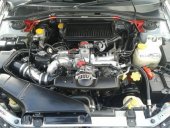
Looks like the Bigger (turbo) and middle (rad) pipes have been swapped over, better routing due to the rotated manifold/relocated header tank.
-
Cheers man, we're all learning as we go. Link wont work or I can't view it. Can you upload it to postimage.org or imgur.com etc.
-
On 24/01/2016 at 11:27 AM, Rome1017 said:
So did you end up rewiring? what connector (or wire) did you find to be the issue and what's your voltage drop now?
The only issue is the OEM 18-16 gauge wiring, already struggling with the OEM fuel pump current draw even at minimum load. Now installing an aftermarket AEM 320L fuel pump, then rewiring.
BE/BH Fuel Pump swap:
http://clubsub.org.nz/forum/showthread.php?45977-Changing-BE-BH-Fuel-Pump&p=615340#post615340
lachlan said:Start the car . Put the meter on the battery . Then put the meter across the fuel pump . Wayyy simpler .Or better yet extend your leads and see what the voltage iscacross the pump when it has to pump against 4 bar when its on boost .
Using the method I've shown you can test voltage drop through the power feed circuit then the ground circuit separately, identifying where the problem is. For example you might not need to rewire completely if you only had a bad earth.
On 25/01/2016 at 7:42 PM, slystiguy said:now install a walbro and see if the pressure drops at idle still

/see if you actually need to hard wire or if the 11v can still run it well enough.
Pretty much every tuner I've talked to recommends hardwiring the fuel pump and using the power wire to trigger a 30amp relay. I guess it's more about eliminating the "what if" situation. The last thing you want is to lean out up the top of rev range eh
The pressure drop seen at idle is because I reconnected the fuel pressure regulator vacuum hose, applying manifold vacuum to the regulator. OEM static fuel pressure of 43.5psi (3bar) is measured with the fuel pressure regulator vacuum hose disconnected.
The trouble with 1V loss at 43.5psi with the fuel pump at minimum load/current draw, is when you add 20psi boost into the fuel pressure regulator. Raising fuel pressure to 63.5psi, increasing the fuel pumps load/current draw. The 1.0V loss will increase substantially, lowering the fuel pumps voltage/flow capabilities at full boost when fuel pressure is most critical.
Planning to fit the new AEM 320L fuel pump and test the voltage drop through the OEM wiring. Then rewire and test voltage drop again.
Will be rewiring as you've described slystiguy. Running bigger power and ground wires with a new relay, using the OEM pump power and ground wires to switch the new relay on and off:
Here's a chart comparing the American wire gauge (AWG) to diameter in MM:

Then a chart showing how much current each thickness/gauge of wire can handle over distance (in feet):

These fuel pump dyno testing write up's by Super Street Online show some common fuel pumps flow rating and current draw at different pressures/loads:
Fuel pump Shootout Part 1: (Walbro 255L)
http://www.superstreetonline.com/how-to/engine/1404-fuel-pump-shootout/
Fuel Pump Shootout Part 2: (DW200-300-65C/AEM320L/OEM130L-145L)
http://www.superstreetonline.com/how-to/engine/1405-fuel-pump-shootout-part-2/
Then finally here's some info on how automotive relays work:
-
Who's Online 0 Members, 0 Anonymous, 64 Guests (See full list)
- There are no registered users currently online
Bh Lack of boost
in Legacy & Outback
Posted
Swapping the injectors over is a lot of work and would normally be a diagnosis last resort. A bad injector can normally be found with a mechanics stethoscope, holding the tip of a screwdriver against the injector and the other end against your ear. A working injector will give a definite ticking noise through the screwdriver, where the dead/sticky injector will be silent or sound completely different.
Check the injector loom plugs as Joker suggested, but most likely dirty spark plugs or a vac/boost leak somewhere. A strong fuel smell with no leaks anywhere suggests it running pretty rich. If new plugs doesn't sort it then it could be O2/MAF/Coolant Temp sensor/IACV.